How Much Tolerance for 3D Printing Is Required for Assembly?
Views: 11 Author: Allen Xiao Publish Time: 2026-02-18


Smashing a plastic prototype with a heavy hammer because the mounting pegs refuse to slide into the designated holes is a deeply frustrating hardware engineering rite of passage. Delivering physical components that fail to mate perfectly on the assembly line destroys tight launch schedules instantly. Procurement executives constantly ask our engineering team how much tolerance for 3d printing is actually mathematically achievable in a real factory environment.
Answering this critical question requires stripping away the inflated marketing statistics published by desktop machine manufacturers. Expecting single-digit micron accuracy straight off a heated build plate completely ignores the violent thermodynamic realities of melting and cooling industrial polymers. Molten plastics inherently shrink as they return to room temperature, warping your carefully designed digital CAD geometry into unpredictable physical shapes.

Executing flawless mechanical assemblies forces hardware teams to master advanced thermal shrinkage compensation algorithms before firing the laser. Designers must aggressively oversize critical holes or deliberately thicken load-bearing walls to combat this unavoidable material contraction. Failing to respect this fundamental chemical physics guarantees catastrophic misalignments during your expensive beta testing phase.
Operating out of the aggressive Shenzhen precision manufacturing hub teaches veterans that additive manufacturing often requires a hybrid approach. Achieving a flawless bearing press-fit often dictates abandoning pure printing and utilizing secondary CNC machining to hit absolute perfection. We must ruthlessly break down exactly where additive geometry succeeds and where subtractive milling becomes absolutely mandatory.
content:
Conquering Thermal Shrinkage Compensation
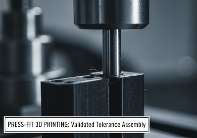
Designing the Perfect Bearing Press-Fit
When Secondary CNC Machining Becomes Mandatory
JUCHENG Hub: Guaranteeing Assembly Success
Frequently Asked Questions: Dimensional Limits
Conquering Thermal Shrinkage Compensation

Do all industrial polymers shrink equally after being extruded from a heated nozzle?
Absolutely not. High-temperature engineering materials like Nylon and ABS suffer from massive thermal contraction compared to standard PLA, requiring aggressive mathematical scaling adjustments prior to printing.
Dealing with thick geometric walls inherently traps massive amounts of heat deep inside the plastic core. While the exterior skin cools and hardens rapidly against the ambient factory air, the molten center continues to shrink slowly over several hours. This severe internal temperature differential physically pulls the external walls inward, creating ugly concave surfaces that ruin flat mating joints.
Intelligent CAM software attempts to counteract this violent physics by deliberately oversizing the entire digital model by one or two percent. However, applying a blanket global scaling factor rarely works for highly complex organic geometries. Thick structural ribs will always contract much harder than thin cosmetic fins, causing severe geometric twisting.
Upgrading to advanced Selective Laser Sintering (SLS) mitigates this nightmare significantly. Because the nylon powder bed remains evenly heated to just below the melting point during the entire build, thermal shock is practically eliminated. Parts cool down uniformly over twenty-four hours, delivering drastically tighter dimensional stability across large automotive enclosures.
Designing the Perfect Bearing Press-Fit

Will a digitally perfect circular CAD hole actually print perfectly round in reality?
Rarely. Layer-based extrusion technologies naturally drag the molten plastic slightly as the toolhead changes direction, almost always resulting in a microscopic oval or egg-shaped hole.
Executing a flawless bearing press-fit demands ruthless design iteration. If an engineer models a ten-millimeter hole for a ten-millimeter steel bearing, the printed hole will inevitably shrink to roughly nine-point-eight millimeters. Attempting to forcefully smash the heavy metal bearing into this undersized cavity will violently split the brittle plastic layers apart.
Factory veterans utilize a highly reliable workaround called undersizing and reaming. Smart designers deliberately draw the CAD hole significantly smaller than required. Once the physical plastic completely cools and hardens, technicians utilize a razor-sharp mechanical hand reamer to shave away the excess material, creating a perfectly round, flawless internal diameter.
Stereolithography (SLA) resin processes offer vastly superior hole concentricity compared to traditional filament extrusion. The laser traces the absolute perimeter mathematically without dragging physical material. However, prolonged exposure to ambient ultraviolet sunlight post-curing can cause the resin to continue shrinking slightly over several weeks.
| Manufacturing Process | Standard Achievable Accuracy | Primary Dimensional Risk | Best Factory Application |
|---|---|---|---|
| FDM Extrusion (Industrial) | ± 0.200 mm to ± 0.500 mm | Z-axis compression and corner warping | Large structural brackets |
| SLA Resin Curing | ± 0.050 mm to ± 0.150 mm | Long-term UV shrinkage over time | Precision fluid manifolds |
| SLS Laser Sintering | ± 0.100 mm to ± 0.300 mm | Thermal distortion on massive flat walls | Complex interlocking gears |
| Subtractive CNC Milling | ± 0.005 mm to ± 0.010 mm | Tool deflection in deep internal pockets | Medical grade bearing housings |
When Secondary CNC Machining Becomes Mandatory

Can additive technologies realistically hit single-digit micron accuracy for aerospace hardware?
Never. Pushing extreme limits strictly requires taking the oversized printed component and physically milling the critical mating surfaces absolutely flat on a rigid machine center.
Executing hybrid manufacturing separates elite hardware programs from amateur projects. Engineers routinely print massive, complex drone chassis out of lightweight nylon to save expensive material costs. However, they deliberately add two extra millimeters of raw material strictly to the engine mounting pads.
Once the plastic completely cures, technicians aggressively clamp the polymer part into a heavy 5-axis secondary CNC machining center. A spinning carbide endmill violently shears away the excess plastic, leaving an absolutely flawless, perfectly flat mounting face. This hybrid workflow guarantees incredible vacuum seals while maintaining the massive weight reduction benefits of additive geometry.
JUCHENG Hub: Guaranteeing Assembly Success

How do procurement managers avoid receiving massive batches of warped, unusable plastic parts?
Partnering with hardcore facilities that execute strict metrology inspections and maintain in-house subtractive capabilities completely neutralizes this massive financial risk.
Jucheng Precision deploys an uncompromising Design for Manufacturing (DFM) audit before your project ever hits the production floor. Our seasoned engineers identify massive thermal masses inside your CAD file and suggest critical hollowing strategies to prevent uncontrollable shrinkage. We calculate the exact physics required to make your parts mate seamlessly.
Operating a massive fleet of automated additive systems directly alongside our heavy milling centers allows us to dominate complex hybrid projects. We print the impossible internal cooling channels and subtractively tap the critical threads under one unified roof, delivering absolute perfection without excuses.
Frequently Asked Questions: Dimensional Limits

Can modifying the internal infill density improve external dimensional accuracy?
Yes. Printing a solid block of plastic traps massive amounts of thermal energy, causing severe external warping. Reducing the internal infill to a geometric honeycomb pattern drastically reduces the thermal mass, allowing the part to cool evenly and hold tighter external dimensions.
Why do extremely tall printed prototypes wobble and lose accuracy near the top?
Tall, skinny components inherently act like a pendulum during the violent extrusion process. As the heavy print bed moves rapidly back and forth, the physical kinetic inertia causes the top of the part to vibrate severely, resulting in heavily shifted and inaccurate upper layers.
Is it mathematically possible to print perfectly sharp external corners?
Extrusion nozzles physical wipe soft plastic around corners, naturally leaving a slight radius. Attempting to force absolute sharpness often results in bulging material. True razor-sharp edges strictly require subtractive secondary milling or aggressive post-sanding.