Industrial 3D Print Wall Thickness Guide for Assembly Lines
Views: 7 Author: Allen Xiao Publish Time: 2026-02-05


Crushing an expensive electronic prototype in your bare hands because the outer shell was designed entirely too thin is a catastrophic failure that delays product launches for weeks. Engineering lightweight, airborne hardware completely forces procurement managers to aggressively shave material off every single component to save battery life. Executing this massive weight reduction safely requires strict adherence to an industrial 3d print wall thickness guide before ever sending the digital file to the factory floor.
Designing extreme thin-walled geometries based purely on desktop software simulations ignores the violent thermodynamic reality of melting physical polymers. Pushing an industrial extrusion nozzle to lay down a zero-point-four millimeter perimeter wall often leaves the structure entirely unsupported from the inside. Relying on blind CAD data without understanding basic material shear strength guarantees your interlocking snap-fits will violently snap off during final assembly.

Mastering exactly how liquid plastics behave under mechanical stress separates elite hardware startups from failed Kickstarter campaigns. Referencing a reliable 3d print wall thickness guide prevents designers from creating impossible microscopic fins that instantly melt or warp during the heavy curing phase. Bypassing these physical limits requires executing highly advanced internal infill strategies to provide a hidden backbone for your fragile cosmetic surfaces.
Operating out of the hardcore Shenzhen precision manufacturing hub gives our engineering teams a massive advantage in defeating these dimensional disasters. When aerospace clients demand impossibly thin profiles that traditional additive technologies cannot mathematically support, veterans deploy heavily integrated subtractive solutions. We ruthlessly identify structural weak points and force hardware teams to respect the brutal physics governing layer adhesion.
content:
Preventing Catastrophic Infill Transition Collapse
Defeating Hydrostatic Resin Blowouts in SLA
Deploying CNC Hybrid Machining for Extreme Limits
JUCHENG Hub: Uncompromising DFM Audits
Frequently Asked Questions: Structural Limits
Preventing Catastrophic Infill Transition Collapse

Why do perfectly smooth external walls suddenly cave inward and reveal the ugly internal honeycomb structure?
This geometric disaster occurs when extreme thin walls lack the necessary solid layers to bridge the wide gaps hiding inside the sparse internal infill, causing the molten plastic to sag violently downward.
Managing volatile infill transition zones requires deep mathematical calibration from the CAM programmer. Designing a functional enclosure with only two perimeter lines is engineering suicide if the interior is mostly hollow air. The outer skin physically requires a dense, underlying foundation to support the heavy molten filament as it rapidly cools and contracts.
Consulting a professional 3d print wall thickness guide reveals that scaling the physical size of a component drastically alters its minimum requirements. A tiny one-millimeter wall works flawlessly on a small customized watch bezel. Applying that exact same thickness to a massive half-meter automotive dashboard guarantees the entire panel will wobble, flex, and permanently bow under its own gravitational weight.
Mechanical engineers aggressively utilize variable density slicing to survive this phenomenon. Instead of thickening the entire heavy part, the software intelligently injects solid plastic specifically behind the fragile cosmetic walls. This advanced programming technique delivers absolute rigid impact resistance while successfully maintaining the critical weight-saving goals of the aerospace client.
Defeating Hydrostatic Resin Blowouts in SLA

Can liquid resin machines print significantly thinner walls than traditional filament extruders?
Yes, the laser can trace microscopic profiles, but pulling those delicate, freshly cured walls out of thick liquid resin creates massive vacuum forces that easily tear the geometry apart.
Experiencing severe hydrostatic resin blowout destroys highly complex medical prototypes instantly. Printing a hollow, cup-shaped fluid manifold traps heavy liquid polymer inside the cavity. As the build plate violently pulls upward, the resulting vacuum suction forces exert terrifying physical pressure against the fragile exterior walls, causing them to literally explode inward.
Escaping this violent fluid dynamic requires drilling strategic escape holes directly into your digital CAD model before exporting. Positioning tiny pressure-relief vents near the base of the design allows the heavy liquid to drain seamlessly during the vertical peeling process. Failing to equalize this intense internal pressure completely nullifies the precision advantages of laser stereolithography.
Ultraviolet curing times dramatically impact the final survival rate of tall vertical geometries. Extremely thin features often remain soft and highly malleable immediately after leaving the chemical vat. Handling these delicate fins before they undergo full post-chamber baking will permanently warp the profile, destroying tight mechanical tolerances before the part even ships.
| Manufacturing Technology | Absolute Minimum Wall | Recommended Structural Wall | Primary Physical Failure Mode |
|---|---|---|---|
| FDM (Thermoplastic Extrusion) | 0.8 mm (Two nozzle widths) | 1.5 mm to 2.0 mm | Delamination and infill sagging |
| SLA (Liquid Resin Curing) | 0.4 mm to 0.5 mm | 1.0 mm to 1.5 mm | Vacuum suction wall rupture |
| SLS (Nylon Powder Sintering) | 0.6 mm to 0.7 mm | 1.2 mm to 2.0 mm | Thermal warpage on large spans |
| DMLS (Direct Metal Laser) | 0.5 mm to 1.0 mm | 2.0 mm+ (Depends on alloy) | Severe heat stress and cracking |
Deploying CNC Hybrid Machining for Extreme Limits

How do aerospace engineers achieve paper-thin polymer profiles without compromising absolute structural density?
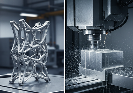
They deliberately bypass pure additive limits by printing the component massively oversized, allowing a rigid CNC milling center to subtractively carve the thick plastic down to the impossible microscopic limit.
Executing highly advanced hybrid manufacturing absolutely destroys the limitations found in any standard 3d print wall thickness guide. When an aviation client demands a zero-point-five millimeter PEEK barrier for a high-temperature fluid sensor, attempting to extrude that geometry directly results in a porous, leaking failure. Additive physics simply cannot pack the molecules tight enough.
Veterans print a solid block of polymer first, ensuring absolute 100% internal density. Technicians quickly transfer this heavy block to a 5-axis milling machine. The spinning carbide endmill violently shears away the excess bulk, achieving an incredibly thin, structurally flawless membrane that effortlessly survives high-pressure testing.
JUCHENG Hub: Uncompromising DFM Audits

Why do so many rapid prototyping facilities blindly print doomed files and charge you for the failure?
Because cheap broker networks lack the localized engineering talent to manually inspect and interrogate the mathematical weaknesses hiding inside your raw CAD data before hitting the start button.
Jucheng Precision absolutely refuses to burn your budget on impossible geometries. Submitting a digital file triggers a merciless Design for Manufacturing (DFM) audit by our senior tooling experts. We utilize advanced software to instantly highlight extreme thin-wall risks, saving you thousands of dollars in wasted iterations.
Owning our entire fleet of industrial machinery empowers our team to seamlessly redirect failing designs. If your requested file violates the physical laws of a 3d print wall thickness guide, we immediately pivot your project toward our heavy CNC division or vacuum casting chambers. We deliver functional hardware, not excuses.
Frequently Asked Questions: Structural Limits

Will increasing the nozzle temperature allow me to successfully print much thinner walls?
No, drastically overheating the polymer actually decreases the molten viscosity, making the material extremely runny. This causes thin unsupported walls to aggressively sag and collapse under their own weight before the cooling fans can solidify them.
Why did my tall vertical fins snap off immediately when I removed them from the build plate?
Extruded filaments possess incredibly poor layer adhesion when stacked vertically as thin standalone towers. Any slight lateral bending force during removal will exploit the weak Z-axis bond, snapping the fragile fin cleanly at the base.
Does printing with carbon fiber filament allow for thinner overall geometry?
Chopped carbon fibers heavily increase the raw rigidity of the plastic, preventing the wall from flexing easily. However, abrasive fibers physically clog smaller nozzles, meaning you often must use a wider diameter nozzle, effectively forcing you to print thicker walls.