


Geometric friction remains the silent saboteur of automated production lines. In the high-velocity world of high-pressure manufacturing, the transition of a plastic part from a liquid state inside a steel cavity to a solid object on a conveyor belt is a violent physical event. If the sidewalls of your part are perfectly vertical, the vacuum seal created between the shrinking plastic and the polished steel becomes unbreakable. The result is a production nightmare: parts that stick, ejector pins that punch through surfaces, and the audible "bang" of a mold struggling to release its contents. Navigating this physical hurdle requires the uncompromising application of an Injection molding design framework, specifically the implementation of a precise injection molding draft angle guide. Draft is the lubricant of geometry; it is the calculated taper that breaks the surface tension and allows a component to glide out of its metallic cage without a single surface blemish. Jucheng Precision recognizes that draft is not a suggestion—it is a mandatory technical contract for manufacturing success.
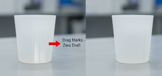
Manufacturing sovereignty dictates that every degree of taper earns its place on the quote sheet. Designing with zero draft is engineering malpractice that leads to "Drag Marks"—ugly vertical scars that ruin cosmetic surfaces and compromise structural integrity. At Jucheng Precision, we don't just "cut steel"; we perform a surgical audit of your 3D CAD files. Our engineers look for the "Release Path," identifying where the cooling plastic will grip the mold core with the most intensity. This guide deconstructs the physics of the 1-degree rule, the critical relationship between surface texture and slope, and the catastrophic consequences of ignoring these fundamental laws. We provide the manufacturing insurance needed to ensure your parts arrive retail-ready, not scarred by the process of their own birth.
Physics of the Taper: Defining the Draft Angle
Engineering Standards: General Rules of Thumb
Texture Sovereignty: Draft Rules for VDI and Mold-Tech
Anatomy of Failure: Consequences of Inadequate Draft
JUCHENG Protocol: The Automated Draft Audit
Physics of the Taper: Defining the Draft Angle
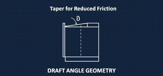
Friction management begins at the drawing board. A draft angle is a slight taper applied to the sidewalls of a part, oriented in the direction of the mold opening. Think of it like a tapered drinking cup: because the top is wider than the base, it slides out of a stack effortlessly. A perfectly cylindrical cup, however, would require significant force to separate. In Injection molding design, as the molten polymer cools, it shrinks. This shrinkage causes the plastic to wrap tightly around the mold "Core" (the B-side of the tool). Without a draft angle, every millimeter of the part's height must be dragged against the steel surface during ejection. This constant metal-on-plastic friction generates heat and mechanical stress. By applying even a 0.5-degree slope, the part is only in contact with the steel for the first few microns of travel. Once the ejection pins push, the part immediately "breaks free" from the surface, floating in the cavity and ensuring a smooth, damage-free release. This physical decoupling is the secret to high-yield manufacturing.
Engineering Standards: General Rules of Thumb
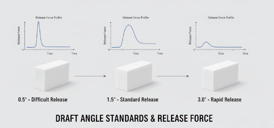
Universal standards exist to protect your project from the "Stick Factor." A professional injection molding draft angle guide mandates a minimum of 1.0 degree on all "A-side" (external) cosmetic surfaces. This is the baseline for smooth, non-textured plastic. However, elite designs often aim for 1.5 to 2.0 degrees to accommodate faster cycle times and reduce the risk of stress whitening around deep mounting bosses. On the "B-side" (internal features like ribs and bosses), draft is even more critical because the plastic shrinks onto these features. Here, a minimum of 0.5 degrees per side is required just to prevent the part from seizing the mold. Jucheng Precision technicians evaluate your material choice—Nylon, for instance, shrinks aggressively and requires more draft than a stable material like ABS. If your design features deep "Zero-Draft" pockets, we may be forced to utilize expensive EDM finishing to reduce friction, driving up your tooling costs. Adhering to these standard ratios ensures that your part doesn't just look good in CAD, but functions reliably on a million-shot production run.
Texture Sovereignty: Draft Rules for VDI and Mold-Tech
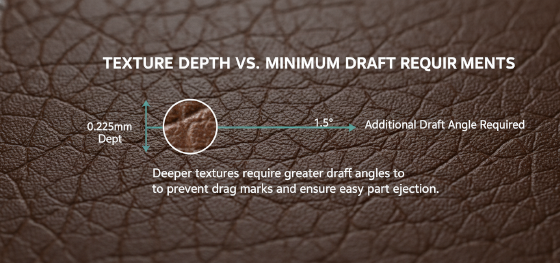
Surface grain acts as a mechanical anchor that defies ejection. If your design specifies a VDI 3400 spark texture or a Mold-Tech leather grain, the "smooth plastic" rules no longer apply. These textures consist of thousands of microscopic pits and valleys etched into the steel. During injection, the plastic is forced into these valleys, creating a high-friction interlocking interface. An injection molding draft angle guide for textured parts must account for the depth of this grain. The industry rule is absolute: for every 0.025mm (0.001 inch) of texture depth, you must add 1.5 degrees of draft to the wall. A heavy leather texture might require a staggering 5 to 7 degrees of taper to release without "Scuffing" the grain. Ignoring this leads to "Shearing"—where the steel effectively grinds the texture off the plastic part during ejection, resulting in shiny, bald spots on your Class-A surfaces. Jucheng Precision partners with the world's leading grain houses to ensure your cosmetic intent is backed by the geometric slope needed to maintain it.
Anatomy of Failure: Consequences of Inadequate Draft
Visual and structural defects are the inevitable children of vertical sidewalls. The most prevalent symptom of inadequate draft is "Drag Marks"—vertical, rhythmic scratches that occur as the part is forced out of the cavity. These marks are not just cosmetic; they are stress risers that can lead to premature cracking in ruggedized housings. Furthermore, inadequate draft forces the "Ejector System" to work harder. In extreme cases, the ejection pins will "Punch Through" the part or cause "Stress Whitening" (crazing) on the opposite side as they struggle to overcome the vacuum seal. This increased mechanical violence also warps the part, as it is still warm and ductile when the pins strike. You end up with a component that is dimensionally out of spec simply because it couldn't exit the tool cleanly. By following the injection molding draft angle guide, you remove this manufacturing hostility, ensuring that every cycle is smooth, every part is pristine, and your tool lasts for its intended lifecycle without suffering from excessive surface wear.
JUCHENG Protocol: The Automated Draft Audit
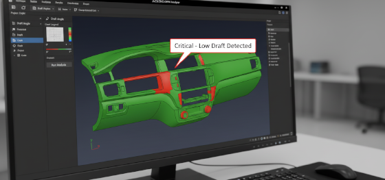
Engineering success at Jucheng Precision is built on the foundation of the proactive DFM audit. We do not wait for the tool to fail during trials; we catch draft issues in the digital space. When you submit a 3D STEP file to our facility, our engineers run an automated "Draft Analysis." This software color-codes your part: green for safe angles, yellow for marginal slopes, and bright red for "Zero or Negative Draft" zones. This digital foresight allows us to propose minor geometry tweaks—such as shifting a parting line or tapering a rib—before a single block of steel is machined. Our integrated facility, equipped with over 150 CNC machines, ensures that the complex tapers we propose are cut with absolute fidelity. Stop guessing if your part will release. Not sure if your wall thickness is uniform or your draft angles are correct? Upload your 3D CAD file to JUCHENG today for a Free DFM Review. Our experts will catch tooling issues before they cost you money, ensuring your transition to mass production is seamless and profitable.

