


Establishing a highly standardized, clear technical blueprint for multi-component assemblies is the only way to guarantee a smooth, error-free assembly run. Creating a robust sheet metal assembly drawing ensures that your manufacturing partner understands the exact spatial relationships, installation sequences, and hardware specifications of your design. This detailed documentation represents a critical milestone in custom sheet metal fabrication, directly determining whether your parts assemble cleanly or suffer from costly delays on the shop floor.
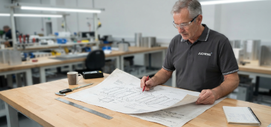
Suffer from loose parts that fail to fit together, missing screws in your shipping boxes, or misaligned mounting threads during final assembly? When 2D drawings are released without clear exploded views, complete bills of materials, or proper welding callouts, the assembly technicians are forced to guess, leading to immediate alignment errors. Proactively configuring your engineering files with standardized mechanical layouts is the best way to secure your product quality.
Let's explore the essential requirements of exploded views and structured material lists, analyze how to properly call out fasteners and welding symbols, and review the benefits of applying geometric tolerancing to critical mating surfaces.
The Importance of Exploded Views and BOMs
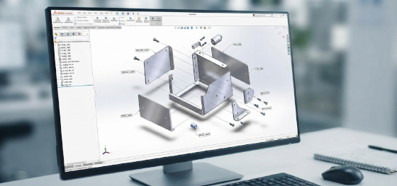
Why are exploded views and structured Bills of Materials critical on assembly drawings?
Exploded views physically isolate nested panels along clear isometric axes, showing assembly technicians the exact spatial routing and mounting paths of every single part.
Attempting to assemble a complex, multi-panel cabinet using only flat, folded 2D views is highly inefficient. If parts are nested closely together, the internal details are hidden, making it difficult to identify which panel mounts first. Exploded views resolve this by physically separating the parts on paper, using clear dotted leader lines to guide the assembly path.
This spatial guide must be paired with a structured Bill of Materials (BOM). A professional BOM is not just a parts list; it must feature specific fields to prevent material shortages. These fields include unique balloon numbers matching the exploded view, manufacturer part codes for third-party hardware, exact quantities, and material specifications, ensuring our technicians can verify every component before assembly begins.
Calling Out Fasteners, Welds, and Hardware Correctly
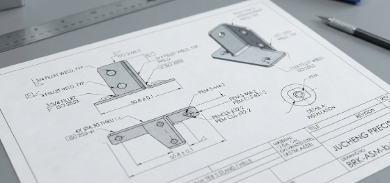
How do you properly document self-clinching hardware and welded joints on your blueprints?
We recommend specifying exact industry-standard part numbers for self-clinching inserts, and utilizing standardized AWS welding symbols directly on joint lines.
A common, costly drafting mistake is writing generic callouts like "add PEM nut" without specifying the exact thread size, material grade, or shank length. Different sheet thicknesses require different clinching profiles. To prevent errors, always specify the exact manufacturer part number (such as PEM S-M3-1) directly on your drawings, ensuring our hardware press operators can load the correct tooling immediately.
Similarly, defining clear welding symbols according to AWS A2.4 standards is vital. A generic arrow pointing to a corner is highly ambiguous, leaving the welder to guess the joint design. Using standard symbols—such as specifying a fillet weld, weld size (throat thickness), and pitch directly on the reference line—ensures high-penetration, solid bonds without thermal warping.
Specifying GD&T for Assembly Mating Surfaces

Why is Geometric Dimensioning and Tolerancing (GD&T) essential for close-tolerance assemblies?
GD&T defines the allowable geometric variations—such as flatness and perpendicularity—on mating surfaces, preventing mechanical interference during final assembly.
Relying strictly on +/- linear dimensions can cause severe cumulative alignment errors on multi-panel enclosures. When multiple parts are welded together, minor angular variations accumulate. This cumulative drift is known as a tolerance stack-up. To prevent assembly bottlenecks, designers utilize GD&T symbols to control critical mating interfaces.
Specifying a tight flatness tolerance (such as within 0.2mm) on the flange where your PCB mounts ensures the board will not bend or short-circuit under mounting screw pressure. Similarly, defining perpendicularity limits on your corner joints ensures that the cabinet door closes flush against the rubber gasket, maintaining high IP65 dustproofing seals. This precise geometric control ensures high assembly yields.
Send Your Assembly Drawings to Jucheng Precision
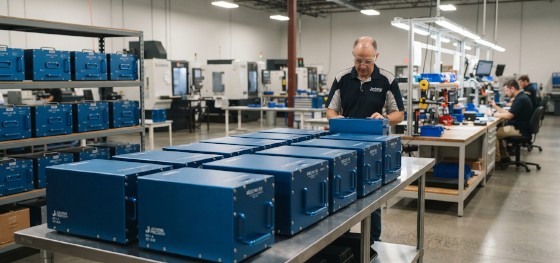
How does Jucheng Precision help engineers optimize their assembly drawing files?
We analyze your 2D blueprints and 3D solid models using advanced DFM engines, checking for thread matches, weld access, and GD&T limits within 24 hours.
Integrating these comprehensive DFM rules, BOMs, and welding symbols into your early sheet metal design cycle is the single most effective way to eliminate assembly bottlenecks. Jucheng Precision houses advanced automated benders, laser cutters, and assembly lines inside our 8000-square-meter facility, ensuring that your parts are cut, folded, painted, and completely integrated under one roof with extreme quality control.
We process a wide range of materials, including lightweight aluminum, high-yield stainless steel, and easily formable carbon steel. Supported by our no MOQ policy and rapid delivery guarantee, we manage your project from initial flat pattern cutting to final, high-durability powder coating and assembly, verifying all dimensions on our advanced coordinate measuring machines (CMM) before final shipping.
FAQ: Critical Questions About Sheet Metal Assembly Drawing
Our engineering team has compiled professional solutions to the most common drafting challenges faced by product developers:
Why are exploded views mandatory on a sheet metal assembly drawing?
Exploded views physically separate nested panels to show our technicians the exact spatial routing, alignment axes, and hardware insertion directions, preventing assembly errors on complex multi-panel builds.How should we call out welding symbols according to AWS standards?
Use standard AWS A2.4 symbols (fillet, spot, or plug welds) directly on joint lines, specifying throat thickness and pitch, allowing the welder to apply consistent, high-penetration bonds.Can we specify both metric and imperial units on the same drawing?
Yes, utilize dual-dimensioning (e.g., mm with inches in brackets) consistently in your CAD title block to prevent shop-floor conversion errors.How does Jucheng Precision expedite engineering reviews using your assembly drawings?
Our technical team analyzes your 2D blueprints alongside 3D solid models, verifying thread fits, weld access, and GD&T limits within 24 hours of submission to deliver a guaranteed manufacturing quote.

