Mold texture draft angle: Engineering the Path of Zero Resistance
Views: 4 Author: Allen Xiao Publish Time: 2026-03-14 Origin: Site


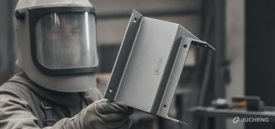
Frictional entrapment remains the primary cause of cosmetic failure in mass production. While industrial designers focus on the tactile allure of a leather grain or a technical matte finish, the manufacturing feasibility of that surface is entirely dependent on a single geometric variable: the Mold texture draft angle. In the uncompromising environment of high-pressure manufacturing, a textured surface acts as a mechanical anchor. As the polymer cools and shrinks onto the mold features, thousands of microscopic "peaks and valleys" in the steel grab the plastic with extreme intensity. If the sidewalls lack the necessary taper, the ejection pins will physically shear the texture off the part, resulting in "Drag Marks"—unsightly vertical scars that ruin the premium identity of your hardware. Navigating the variables of Injection molding surface finishes requires moving beyond visual intent and adopting a dispassionate, mathematical approach to release physics. Jucheng Precision operates as a high-fidelity DFM sanctuary, ensuring every degree of slope is calculated to protect your cosmetic investment.

Manufacturing sovereignty is earned through the management of "Side-Wall Interference." Amateurs often apply a universal 1-degree draft to their parts, unaware that adding a Mold-Tech or VDI texture can double or triple the required slope. Failing to account for grain depth during the CAD phase is a strategic error that leads to stuck parts, warped geometries, and permanent tool damage. Jucheng Precision eliminates these "De-molding Disasters" by performing a surgical texture audit on every STEP file before a single chip of steel is cut. We map your chosen grain to its physical displacement, ensuring your parts glide out of the cavity with zero scuffing. This guide deconstructs the physics of mechanical interlocking, the mandatory "1.5-degree rule," and why JUCHENG’s automated draft analysis is the mandatory insurance policy for high-yield hardware launches.
content:
Mechanical Interlocking: The Physics of Texture Resistance
Mathematical Guardrails: The 1.5-Degree-per-Mil Rule
Scale of Severity: VDI and Mold-Tech Draft Requirements
Anatomy of Failure: Drag Marks and Tool Scuffing
JUCHENG Protocol: Automated 3D Draft Integrity Audits
Mechanical Interlocking: The Physics of Texture Resistance

Release dynamics in textured molds are governed by the friction of micro-obstructions. When molten plastic—such as ABS or Polycarbonate—is injected into a tool, it perfectly replicates the surface of the steel. In a textured tool, the plastic flows into every microscopic pit. As the material cools, it undergoes volumetric shrinkage, which causes it to wrap tightly around the internal features (the mold core). If the sidewalls are perfectly vertical, every single "peak" of the texture in the steel acts as a hook, physically preventing the part from moving upward. This "Mechanical Interlocking" is why a textured part requires significantly more force to eject than a smooth one. A proper Mold texture draft angle solves this by creating a geometric decoupling. As soon as the part moves even a few microns during ejection, the taper increases the gap between the plastic and the steel, instantly breaking the interlock. Without this slope, the ejection system is essentially trying to pull a jagged rock through a tight pipe—a process that inevitably results in surface destruction.
Mathematical Guardrails: The 1.5-Degree-per-Mil Rule

Numerical certainty is the only defense against de-molding scuffs. While a standard smooth part can often function with 0.5 to 1.0 degrees of draft, textures demand a far more aggressive slope. Jucheng Precision engineers utilize the "1.5-Degree Rule" as an absolute technical standard: for every 0.025mm (0.001 inch or "mil") of texture depth, you must add 1.5 degrees of draft angle to your part's sidewalls. This is additive to the baseline draft required for the material itself. For instance, if you select a standard leather grain with a depth of 0.075mm (3 mils), the Mold texture draft angle must be at least 4.5 degrees (3 x 1.5°) plus the base 1 degree, totaling 5.5 degrees of taper. Ignoring this math is a guarantee of manufacturing scrap. We advocate for "Conservative Designing," where designers prioritize the release angle over the pursuit of verticality, ensuring the part reaches the consumer with its cosmetic integrity uncompromised by the violence of the ejection cycle.
Scale of Severity: VDI and Mold-Tech Draft Requirements

Standardized haptic libraries provide a clear roadmap for required tapers. Whether you are utilizing the European VDI 3400 scale or the North American Mold-Tech (MT) system, the deeper the grain, the higher the draft penalty. Jucheng Precision provides the following reference matrix for common Injection molding surface finishes to assist in early-stage design routing:
| Texture Standard | Typical Depth (µm) | Minimum Draft (°) |
|---|---|---|
| VDI 18 (Fine Matte) | 0.80 µm | 1.5° |
| VDI 24 (Standard Matte) | 1.60 µm | 2.5° |
| VDI 33 (Coarse Spark) | 4.50 µm | 4.5° |
| MT-11010 (Fine Grain) | 25 µm | 3.0° |
| MT-11050 (Heavy Leather) | 115 µm | 7.0°+ |
Choosing a heavy grain like MT-11050 without realizing it requires 7 degrees of draft is a common budget killer. At Jucheng Precision, we advocate for "Strategic Grain Placement." If your design cannot support the high draft angles of a deep texture, we recommend shifting to a finer VDI 21 finish on those specific walls while maintaining the aggressive texture on the floor of the part. This hybrid approach protects your aesthetic vision without triggering ejection failures.
Anatomy of Failure: Drag Marks and Tool Scuffing

Surface scars are the permanent evidence of inadequate geometry. When the Mold texture draft angle is insufficient, the first few cycles of a mold trial will produce "Drag Marks"—vertical streaks that appear as if someone has scratched the part with a wire brush. These marks occur because the part is still warm and ductile as it is being forced out. The steel texture effectively plows through the plastic surface. Beyond the aesthetic rejection, drag marks indicate excessive wear on the tool itself. The sharp edges of the grain in the steel will eventually round off or "Grip" the plastic so tightly that it causes the mold to "Seize." This leads to catastrophic downtime and expensive mold repair. Jucheng Precision eliminates this risk by utilizing 5-axis CNC machining to ensure our tapers are perfectly smooth and consistent, reducing the coefficient of friction and ensuring that the only thing moving during ejection is the plastic part, not the tool steel's integrity.
JUCHENG Protocol: Automated 3D Draft Integrity Audits
Engineering excellence at Jucheng Precision is built on the foundation of predictive manufacturing. We don't just "hope" your textured parts look good; we verify them in the digital space. When you upload a CAD file to our facility, our veteran engineers perform a comprehensive 3D Draft Audit. Our software color-codes every face of your part, flagging areas that are unsafe for your selected VDI or MT texture. We provide specific geometry modifications—recommending a wall-tilt or a parting-line shift—before a single chip of steel is cut. Our integrated facility, housing over 150 CNC machines and elite injection bays, ensures that the complex tapers we propose are executed with sub-micron fidelity. Stop gambling your cosmetic success on vertical walls. Not sure if your draft angles support a VDI 33 finish? Upload your 3D CAD file to JUCHENG today for a Free DFM Review. Our experts will identify Injection molding surface finishes bottlenecks before they cost you money, ensuring your transition to production is seamless, consistent, and retail-ready.


ㆍPrivacy: We respect your privacy. Here you can find an example of a non-disclosure agreement. By submitting this form, you agree to our terms & conditions and privacy policy.