


Designing highly complex industrial cabinetry, medical analyzer housings, or aerospace bracket arrays involves managing minor dimensional shifts across multiple manufacturing cells. Specifying realistic sheet metal fabrication tolerances represents the ultimate engineering safety net, directly determining whether your multi-component assemblies slide together cleanly or bind on the integration line. This turnkey sheet metal fabrication process requires a seamless understanding of how cutting, folding, welding, and painting build cumulative dimensional variations.
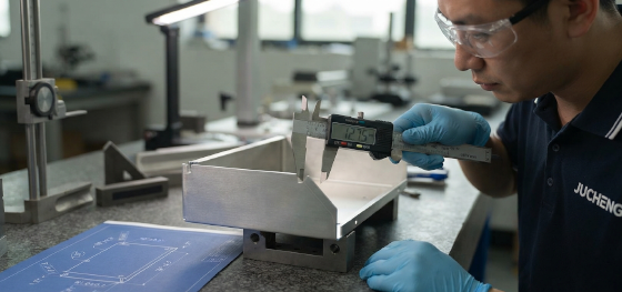
Suffer from unexpected delays and bloated assembly bills because your finished panels fail to align on the shop floor? When drawings are modeled without analyzing how mechanical tolerances stack up from process to process, it forces assembly technicians to run manual deburring and grinding, driving up your labor costs. Proactively integrating material-specific thickness deviations and coating thicknesses into your unfolding models is the best way to secure your product quality.
Let's examine how minor process variations build a cumulative tolerance stack-up, analyze the thermal shrinkage variables of structural welding, and explore how to calculate paint film thickness offsets to maintain precise mechanical clearances.
Why Cumulative Tolerances Matter in Assembly

What is tolerance stack-up and how does it compromise custom multi-panel assemblies?
Tolerance stack-up is the mathematical accumulation of individual process errors across consecutive cutting, bending, and joining steps, which can misalign final bolt holes.
To ensure high assembly yields, understanding the cumulative impact of process variations is critical. When a flat pattern is cut, folded, and welded, it inherits minor dimensional deviations at every single workstation. We define this physical compounding of errors as a tolerancestack-up.
If a design features five consecutive folded flanges, and each bend exhibits a standard commercial tolerance of ±0.3mm, the final flange can drift by up to ±1.5mm from its nominal coordinate. This cumulative drift will misalign critical mounting holes, making it impossible to install slide-in rails or circuit boards. To prevent stack-up failures, our programmers utilize advanced geometric tolerancing (GD&T) to establish master datum planes, limiting the total accumulated drift.
Welding Tolerances and Shrinkage

How does structural welding heat warp and shrink custom sheet metal assemblies?
The intense heat of an electric arc melts joint seams, inducing localized thermal contraction upon cooling that pulls adjacent panels out of tolerance.
Structural MIG/TIG welding is a highly intense thermal process that presents unique challenges for tight-tolerance designs. As the liquid weld bead solidifies, it undergoes a predictable volumetric contraction known as welding shrinkage. This localized contraction pulls the joined sheets inward, typically causing an angular distortion of 1 to 2 degrees and a linear shrinkage of approximately 0.5% to 1.5% across the joint.
To manage these thermal distortions, our certified welders utilize heavy-duty clamping fixtures and progressive stitch-welding techniques to distribute the heat input evenly. We also pre-compensate for this contraction in our CAD models, designing our flat patterns with deliberate dimensional offsets so that the cooled, welded assembly relaxes exactly into your target tolerances.
How Surface Finishes Change Dimensions

How does electrostatic powder painting alter the physical dimensions of finished panels?
Powder coating adds a physical polymer layer of 60 to 120 microns per side, requiring designers to subtract these film thicknesses from mating slip joints.
A common, costly design mistake is neglecting the thickness of secondary surface coatings on critical mating interfaces. Applying a high-durability electrostatic powder coating builds a robust barrier of 60 to 120 microns (2.4 to 4.7 mils) on every single surface. For a tight-tolerance slip joint or an interlocking hinge, this coating thickness essentially doubles, adding up to 0.24mm of physical material.
If your CAD model specifies zero clearance on mating tabs or hinge pins, the finished painted parts will bind or fail to assemble completely. To prevent these assembly bottlenecks, we recommend including deliberate clearance offsets on all coated flanges, or utilizing high-temperature silicone masking tapes to block paint buildup on critical grounding pads and threaded holes, delivering clean, ready-to-use enclosures.
| Fabrication Process | Standard Commercial Tolerance | Surface Finish Dimensional Impact |
|---|---|---|
| Fiber Laser Slicing | ±0.15 mm (Standard laser kerf limit) | Zero (No dimensional changes) |
| Press Brake Bending | ±0.3 mm / ±1.0° (Air bending default) | Zero (No dimensional changes) |
| MIG / TIG Welding | ±1.5 mm (Subject to thermal shrinkage) | Warping (Alters flat sheet profiles) |
| Electrostatic Powder Coating | Zero (Processing tolerances only) | +60 to 120 microns (Applies thick dry film) |
Turnkey Enclosure Fabrication at Jucheng Precision

How does Jucheng Precision control tight tolerances across complex, multi-stage projects?
We operate high-power fiber lasers, automated press brakes, and in-house powder coating lines under a unified quality system, checking alignments at every gate.
Why risk your project tolerances on suppliers who outsource their finishing and assembly? At Jucheng Precision, we manage every single stage of your custom project under one roof. This integrated process capability keeps our overall sheet metal tolerances remarkably low, ensuring that your parts are cut, bended, welded, and painted with zero dimensional drift.
We process a wide range of raw sheets, including lightweight aluminum, high-yield stainless steel, and easily formable carbon steel, matching each to its mathematically calculated springback allowances. Our technical department provides a 24-hour free DFM analysis to check your CAD models, checking tolerances and tool clearances before production. Supported by our no MOQ policy and rapid delivery guarantee, we manage your project from initial flat pattern cutting to final packaging and assembly.
FAQ: Critical Questions About Sheet Metal Fabrication Tolerances

Our engineering team has compiled professional solutions to the most common quality and cost challenges faced by product developers:
What is the standard tolerance for general sheet metal fabrication?
Under standard commercial norms (such as ISO 2768-m), the standard tolerance for general sheet metal fabrication is approximately ±0.3mm for linear dimensions under 120mm, and ±1.0 degree for angular bends. These limits are highly cost-effective to manufacture, but high-end enclosures often require tighter custom tolerances down to ±0.1mm and ±0.5 degrees, which we achieve using advanced bottoming dies.Why do steel, aluminum, and galvanized steel have different tolerances for the same gauge?
Different materials utilize separate raw rolling systems at the mill, resulting in different raw thickness tolerances. For example, a 16-gauge galvanized steel sheet is slightly thicker than standard cold-rolled steel due to its protective zinc coating. Our programmers calibrate our unfolding software using material-specific thickness tolerances to ensure that your flat patterns are cut precisely.Does a tight dimensional tolerance always increase custom manufacturing costs?
Yes, absolutely. Demanding tolerances tighter than standard commercial limits forces the shop to run secondary manual adjustments, slows down machine feed rates, and requires continuous CMM dimensional checks, driving up your labor costs. We recommend utilizing standard commercial tolerances wherever possible and only specifying tight tolerances for critical mating interfaces.How does Jucheng Precision prevent cumulative errors from throwing high-volume orders out of tolerance?
We execute rigorous quality control gates across our finishing line, utilizing advanced non-destructive coordinate measuring machines (CMM) to measure the dimensions at multiple points. Our technicians monitor bath chemistry and current densities in real time, ensuring that every finished component meets your strict thickness and salt-spray resistance requirements.

