


Establishing consistent quality boundaries before releasing custom blueprints to production is essential to managing product development costs. Adhering to standard sheet metal tolerances ensures that your custom brackets, multi-panel chassis, and industrial cabinets can be manufactured repeatably across different workshops without requiring extensive manual fitting. This universal coordination is a critical milestone in custom sheet metal fabrication, directly determining whether your manufacturing partners can interpret your geometric requirements cleanly.

Suffer from high part rejection rates and infinite communication loops due to missing or overly strict tolerance callouts on your designs? When engineers model hardware without specifying standard, realistic limits, it forces estimators to assume the tightest possible classes, artificially inflating your manufacturing costs. Aligning your custom designs with standard commercial limits is the best way to secure your product margins.
Let's explore why universal manufacturing guidelines are necessary to reduce transaction friction, analyze the specific dimensional classes of the widely accepted ISO 2768 standard, and review how to properly specify tolerance parameters on your active CAD drawings.
Why Do We Need Universal Sheet Metal Tolerance Standards?
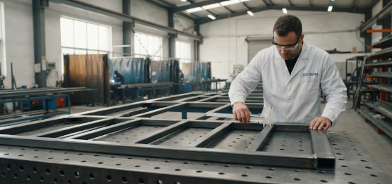
Why are international tolerance standards essential for custom manufacturing contracts? Universal standards establish a common technical language between product designers and manufacturing facilities, eliminating ambiguous dimensions and securing clear quality benchmarks.
Without globally recognized standard sheet metal tolerances, every single drawing would require hundreds of individual tolerance callouts, making blueprints incredibly cluttered and difficult to read. It would also leave the buyer and fabricator with different assumptions about how un-toleranced features should be inspected.
State the applicable standard, edition and class in the drawing, and confirm them during quotation review. General tolerances apply within the scope of the selected standard; they do not replace individual callouts, a defined inspection method or review of process capability.
A Deep Dive into ISO 2768
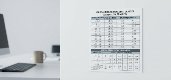
What is the structure of the ISO 2768 standard, and which tolerance classes apply to sheet metal? ISO 2768-1:1989 addresses linear and angular dimensions without individual tolerance indications. The older geometrical-tolerance document, ISO 2768-2:1989, has been withdrawn; ISO lists ISO 22081:2021 as its replacement. Identify which document and edition the drawing actually invokes.
The most widely accepted standard for general sheet metal tolerances is ISO 2768. This standard is designed to simplify drawings by defining clear, scale-dependent permissible variations. Part 1 defines tolerances for linear dimensions and angular dimensions, dividing them into four accuracy classes: fine (f), medium (m), coarse (c), and very coarse (v).
Class m is one possible drawing requirement, not an automatic default for every sheet metal part. Select the class according to function and confirm that the fabricator can meet it. This excerpt illustrates linear size bands; it does not cover every feature or replace the complete standard:
| Dimension Segment | Fine Class (ISO 2768-f) | Medium Class (ISO 2768-m) | Coarse Class (ISO 2768-c) |
|---|---|---|---|
| 0.5 mm to 3 mm | ±0.05 mm | ±0.10 mm | ±0.20 mm |
| Over 3 mm to 6 mm | ±0.05 mm | ±0.10 mm | ±0.30 mm |
| Over 6 mm to 30 mm | ±0.10 mm | ±0.20 mm | ±0.50 mm |
| Over 30 mm to 120 mm | ±0.15 mm | ±0.30 mm | ±0.80 mm |
Specifying Tolerances on Your CAD Drawings
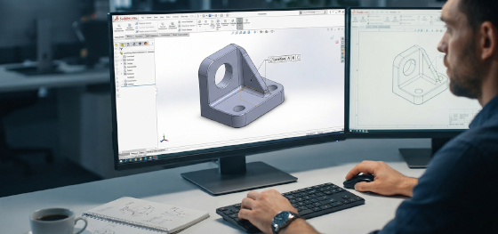
How should design engineers properly document general and custom tolerances on their engineering drawings? We recommend writing the selected general standard directly inside the title block, and reserving tight, custom tolerances strictly for critical mating interfaces.
A tighter tolerance can change process selection, setup and inspection cost, but there is no universal percentage premium. Ask the fabricator which dimensions drive the quotation. Retain requirements needed for fit and function, and review unnecessarily tight callouts on non-critical features.
A drawing note can identify the agreed general dimensional tolerance, for example ISO 2768-1:1989, class m. Check the standard's scope and exceptions before applying it to a feature. Hole size, hole position, flatness and bend angle are different requirements: a linear size tolerance alone does not define them all. Specify critical mating interfaces, datums and geometrical controls individually where function requires them.
Jucheng Precision Meets and Exceeds Global Standards

How does Jucheng Precision consistently achieve and exceed strict global tolerance standards? We combine advanced multi-axis fiber lasers and CNC press brakes with an in-house quality control team equipped with high-end coordinate measuring machines.
Why compromise on accuracy when seeking cost-effective custom parts? At Jucheng Precision, we manage every single fabrication stage under a unified quality system. This integrated capability keeps our overall sheet metal tolerances remarkably low, ensuring that your parts are cut, bended, and assembled with extreme consistency.
We process a wide range of materials, including lightweight aluminum, high-yield stainless steel, and easily formable carbon steel during high-precision sheet metal fabrication cycles. Our technical department provides a 24-hour free DFM analysis to check your CAD models, checking tolerances and tool clearances before production. Supported by our no MOQ policy and rapid delivery guarantee, we manage your project from initial flat pattern cutting to final, high-durability packaging and assembly.
FAQ: Critical Questions About Standard Sheet Metal Tolerances
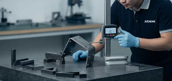
Our engineering team has compiled professional solutions to the most common quality and cost challenges faced by product developers:
- What is the standard tolerance for standard sheet metal tolerances in general B2B projects? There is no single tolerance for every dimension below 120 mm. Under the class m linear-size excerpt above, a 10 mm dimension falls in the over 6–30 mm band (±0.2 mm), while a 100 mm dimension falls in the over 30–120 mm band (±0.3 mm). Angular tolerances use a separate table and depend on the relevant length; do not assign ±1° to every bend.
- Why do steel, aluminum, and galvanized steel have different tolerances for the same gauge? Different materials utilize separate raw rolling systems at the mill, resulting in different raw thickness tolerance bands. For example, a 16-gauge galvanized steel sheet is slightly thicker than standard cold-rolled steel due to its protective zinc coating. Our programmers calibrate our unfolding software using material-specific thickness tolerances to ensure that your flat patterns are cut precisely.
- Does a tight dimensional tolerance always increase custom manufacturing costs? Not always. A tighter requirement adds cost when it changes the process, yield, setup or inspection needed for that feature. Discuss the actual drawing and inspection plan rather than assuming every tolerance change has the same cost effect.
- How does Jucheng Precision prevent thickness variations from affecting the standard sheet metal tolerances? We bypass raw material variations by sourcing only premium, mill-certified steel coils with tight thickness tolerances. Our quality control team continuously measures the incoming sheets using calibrated digital micrometers, and inputs these real measurements into our CAD unfolding systems, ensuring that our progressive calculations and tool setups are perfectly matched to the actual metal thickness.
Using the ISO 2768 Reference PDF with Your Drawing
The general tolerances reference PDF is a quick-reference summary. It is not a Jucheng inspection report or a substitute for the complete standard. Read it together with the drawing revision and individual tolerance callouts.
Illustrative drawing check, not a customer case: If a drawing invokes class m for a 10 mm linear dimension within the standard's scope, the ±0.2 mm band gives limits of 9.8–10.2 mm. A separate 100 mm dimension with ±0.3 mm gives 99.7–100.3 mm. These size limits do not establish hole position or flatness. Mark those requirements separately where assembly function needs them.
For a formed bracket, identify whether a dimension is inspected in the flat or formed state, which surfaces locate the part, and whether coating is included. An assembly can fail even when individual dimensions pass if the datum scheme or tolerance accumulation was not reviewed.
Standard status checked 29 September 2026: ISO 2768-1:1989 remains listed as published, with a revision under publication. ISO 2768-2:1989 is withdrawn and ISO identifies ISO 22081:2021 as its replacement. Review legacy drawing notes before changing them; a newer document does not automatically change the requirements of an existing approved drawing.

