Validating mechanical fitments on a digital model is never a complete substitute for physical stress testing. Utilizing rapid sheet metal prototyping allows engineers to identify unexpected assembly interferences, check connector alignments, and verify structural rigidity before committing significant capital to mass production. This critical developmental phase ensures that physical sheet profiles behave predictably under real-world loads.

Many hardware teams face devastating launch delays when their first factory-stamped housings arrive with misaligned mounting holes or structural weaknesses. Re-machining custom progressive dies to fix a 1mm design mistake is an incredibly slow, expensive process that can stall a product launch for months. Catching these geometric mismatches early on physical test units completely removes these risks.
Let's analyze how physical prototypes expose critical tolerance stack-ups, examine the benefit of non-tooling cutting and bending for short runs, and review how to transition your designs seamlessly from initial test sheets to production-ready hardware.
content:
Why Prototyping is Crucial for Sheet Metal Design
No Tooling Required: The Power of Laser Cutting and CNC Bending
Transitioning from Prototype to Low-Volume Production
Get Your Sheet Metal Prototypes in Days with JUCHENG
FAQ: Critical Questions About Sheet Metal Prototyping
Why Prototyping is Crucial for Sheet Metal Design

What design flaws can physical sheet metal prototypes expose?
Physical prototypes identify critical assembly clashes, thermal heat-dissipation bottlenecks, and thread stripping issues that automatic CAD interference checks often miss.
A 3D CAD model displays geometric dimensions with perfect mathematical precision, but it cannot simulate the physical behavior of metal grain boundaries or manual assembly variances. When folded flanges are mounted together, minor angle drifts accumulate, resulting in a severe interference fit. Physical prototyping exposes these tolerance stack-ups, allowing you to widen mounting slots before releasing drawings.
Furthermore, mounting internal components like fans, heat sinks, and PCB boards into a physical metal chassis allows you to verify real-world cable routing, access clearances for hand tools, and validate electromagnetic shielding. This hands-on validation ensures that your hardware is easy to assemble on the final integration line.
No Tooling Required: The Power of Laser Cutting and CNC Bending

How do manufacturers keep sheet metal prototyping costs so low?
We bypass expensive custom die expenses by utilizing software-driven fiber laser cutting and programmable press brakes to fabricate custom parts directly from CAD profiles.
By utilizing non-tooling cutting and folding methods, rapid sheet metal prototyping bypasses the massive NRE setup fees associated with custom hard dies. Instead of machining dedicated steel punches, flat patterns are cut on advanced laser cutting systems, which slice intricate perimeters with zero physical tooling contact.
The flat sheets are then formed on programmable press brakes. This CNC bending process utilizes standard V-die and punch sets to execute multiple folds in sequence, adjusting back gauges automatically for each step. This software-driven workflow allows us to implement design changes instantly, simply by updating the flat pattern CAD file, keeping your prototype expenses exceptionally low.
Transitioning from Prototype to Low-Volume Production

What is the best way to move custom designs from prototyping to continuous manufacturing?
We optimize this transition by implementing a modular die strategy, allowing designs validated on laser cutting setups to move seamlessly to low-volume stamping without dimensional drift.
Transitioning custom hardware from a single flat blank to continuous output is the most critical bridge of the sheet metal fabrication process, requiring a balanced tooling strategy. Running laser cutting and CNC bending is ideal for validating designs under 500 units. However, once your volume demands scale, transitioning to custom hard stamping dies is necessary to drive per-part costs down to pennies.
| Production Stage | Primary Processing Path | Average Lead Time | Tooling Investment (NRE) |
|---|---|---|---|
| Functional Prototyping | Laser Slicing + Press Brake Bending | 4 to 7 Days | Zero (No dies required) |
| Low-Volume Runs | CNC Punching + Rapid Modular Tooling | 7 to 15 Days | Low (Pre-machined master bases) |
| Continuous Production | Progressive / Matched Stamping Dies | 15 to 30 Days | High (Hardened tool steel dies) |
By managing both prototyping and production tooling under one roof, we eliminate dimensional discrepancies. Our engineers reuse the flat CAD offsets verified during the prototyping phase to design our progressive dies, ensuring that your low-volume production units match the physical characteristics of your approved prototypes.
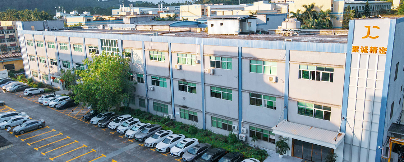
Get Your Sheet Metal Prototypes in Days with JUCHENG

How does JUCHENG expedite the development cycle of custom prototype enclosures?
We run high-precision laser cutters and multi-axis brakes backed by an automated DFM engine, validating blank dimensions and edge clearances in hours.
Why wait weeks for a simple test bracket? JUCHENG houses a dedicated rapid prototyping cell designed specifically for fast-turnaround product development. We combine high-speed laser blanking with advanced bending setups, allowing us to move from 3D models to completed physical parts in record time.
We stock a wide selection of raw sheet metals to support your functional testing, including lightweight aluminum, high-yield stainless steel, and easily formable carbon steel. Our technical department provides a 24-hour free DFM analysis, evaluating your flat patterns to eliminate bend tearing and interference issues before we cut metal. Backed by our no MOQ policy and rapid delivery guarantee, we manage your prototypes from initial cad unfolds to final surface powder coating.
FAQ: Critical Questions About Sheet Metal Prototyping

How do you verify mounting hole alignments on folded prototypes?
We verify alignments during our digital DFM review by simulating the physical folding steps, and then validate the physical parts using coordinate measuring machines. This ensures that the mounting holes align perfectly with the target component coordinates.
Why is it difficult to prototype tight bends on high-strength steels?
High-strength steels possess low ductility and high springback rates, meaning the material resists bending and is prone to outer-edge cracking under tight radii. To resolve this, we increase the punch radius and adjust our blank orientation relative to the rolling grain direction of the plate.
What causes sheet warping near laser-cut slot clusters?
Concentrated laser cutting on thin sheets can introduce high localized heat, causing the metal to warp. To prevent this, our CNC programmers optimize cutting paths to distribute thermal energy evenly across the sheet, or we utilize mechanical turret punching for dense hole clusters to keep the part flat.
What is the best material choice for initial functional trials?
For lightweight structural enclosures, we recommend aluminum 5052-H32 due to its excellent ductility and corrosion resistance. For components requiring maximum tensile strength, stainless steel 304 or carbon steel SPCC are the standard choices. Our technical team supports rapid sheet metal prototyping with a comprehensive material library to match your design requirements.