Why Does Ignoring Die Casting Machining Allowance Destroy Tooling?
Views: 1 Author: Allen Xiao Publish Time: 2026-06-03


Relying strictly on raw metal injection to seal high-pressure fluids guarantees catastrophic leaks. Hardware designers frequently expect heavy steel molds to produce perfectly flat O-ring grooves straight out of the press. Liquid alloys shrink unpredictably, leaving raw surfaces slightly wavy and entirely unsuitable for critical mating components. Leaving a precise die casting machining allowance on your CAD files solves this limitation perfectly. Subtractive milling shaves this intentional excess metal away, delivering absolute zero-gap perfection without blowing up your tooling budget.

Removing too much material triggers an entirely different manufacturing disaster. Scraping past the dense outer skin of the raw part immediately exposes horrifying internal gas bubbles that destroy sealing integrity completely. Following a rigorous die casting design guide forces your engineering team to balance subtractive cutting depths against internal metallurgical realities before any steel is milled.
Slashing secondary production costs requires locking down this exact mathematical balance. Let's explore why cutting into the core destroys structural integrity, exactly how much excess metal you should leave behind, and why separating your foundry from your CNC shop destroys accountability.
content:
Secondary Operations: Perfecting Raw Metallurgy
Porosity Trap: Penetrating the Chill Zone
Mathematical Limits: Leaving the Perfect Amount
Common Features: Tapped Holes and Mating Faces
Turnkey Factory: Seamless Subtractive Integration
FAQ: Honest Answers About Drill Bits and Yield Strength
Secondary Operations: Perfecting Raw Metallurgy

Why must hardware teams actively plan for secondary subtractive milling?
Raw injection physically cannot hold the microscopic tolerances required for complex bearing journals or watertight hydraulic channels, making high-speed post-machining absolutely mandatory for commercial survival.
Relying exclusively on the initial mold output limits your commercial applications severely. Mating delicate circuit boards requires perfectly flat mounting surfaces that only a rapidly spinning drill bit can physically guarantee.
Planning for this inevitable post-processing prevents unexpected budget explosions later. You simply add a fraction of a millimeter of sacrificial metal to specific areas, creating a highly predictable safe cutting zone for the factory operators.
Porosity Trap: Penetrating the Chill Zone

What happens when CNC cutters dig too deeply into the raw hardware?
Milling past the hardened outer skin completely exposes the softer, sponge-like internal core, immediately ruining the cosmetic finish and destroying critical sealing grooves with tiny air voids.
Liquid metal freezes violently against the cold steel mold, creating a highly dense, extremely strong exterior armor known as the chill zone. This crucial outer layer generally measures barely a single millimeter thick.
Shaving off two millimeters of metal completely obliterates this protective shield. Pushing your die casting machining allowance too deep guarantees your cutting tools will hit massive air pockets, instantly scrapping the component and halting assembly.
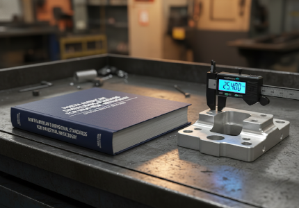
Mathematical Limits: Leaving the Perfect Amount

How much sacrificial material should engineers actually add to the blueprint?
Industry experts typically recommend leaving exactly 0.5mm to 1.5mm of extra material on critical faces, providing just enough bite for the cutter without breaching the porous core.
Leaving too little material creates a frustrating manufacturing nightmare. If the spinning cutter barely grazes the surface, it simply rubs and smears the metal rather than slicing it cleanly, drastically accelerating expensive tool wear.
| Feature Geometry | Recommended Sacrificial Depth | Primary Engineering Reason |
|---|---|---|
| Flat Mating Surfaces | 0.5mm to 1.0mm | Clears thermal warpage for perfect zero-gap sealing. |
| Threaded Internal Bores | Cored smaller, then tapped | Provides solid wall material for high-strength screw threads. |
| Deep Blind Cavities | Drilled entirely via CNC | Prevents fragile steel mold pins from snapping under pressure. |
Common Features: Tapped Holes and Mating Faces

Handling internal threads demands brutal honesty regarding metallurgical limits. Trying to inject perfectly formed microscopic screw threads directly into the part almost always fails due to chaotic thermal shrinkage.
Engineers successfully integrate die casting bosses and holes by casting them as smooth, solid cylinders initially. Adding a precise mathematical allowance ensures the CNC taps have enough solid wall thickness to carve flawless threads later.
Sealing grooves mandate this exact same hybrid strategy. You pour the rough channel quickly to save tooling costs, then execute a final high-speed milling pass to guarantee absolute watertight compression.
Turnkey Factory: Seamless Subtractive Integration

Why does splitting your supply chain ruin tight manufacturing tolerances?
Sending rough parts to a separate machine shop eliminates accountability; if the secondary shop mills into a hidden void, they will instantly blame the foundry, leaving you paying for the ruined batch.
Operating our massive turnkey precision hub completely destroys this logistical friction. We inject the raw hardware, verify the internal density using X-ray scans, and load the parts directly into our own 5-axis cutting centers seamlessly.
Stop risking your high-end commercial assemblies on disjointed vendors. Send your intricate CAD files to our engineering department today for a ruthless DFM audit, securing flawless hybrid manufacturing without supply chain delays.
FAQ: Honest Answers About Drill Bits and Yield Strength
![]()
Does adding excess material drastically increase the initial tooling costs?
No. Carving the steel cavity slightly larger requires minimal extra spindle time during the initial mold creation, making it a financially invisible upgrade for your procurement team.
Will aggressive milling alter the structural yield strength of the part?
Only if you cut dangerously deep into the porous core. Removing the recommended fraction of a millimeter leaves the structural integrity completely intact and fully verified for field deployment.
Can factory operators dynamically adjust the cutting depth on the fly?
Modern 5-axis centers utilize optical probing to measure the exact shape of the raw casting before the drill bit descends, dynamically adjusting the toolpath to compensate for minor thermal warpage.
Why do some machined surfaces look dull and smeared instead of shiny?
Dull, smeared finishes typically indicate that the designer left too little excess metal, forcing the cutter to aggressively drag across the tough chill zone instead of slicing through it cleanly.