Die Casting Design Guide: Stop Designing Impossible Metal Hardware
Views: 1 Author: Allen Xiao Publish Time: 2026-06-01 Origin: Site


Sending an untested 3D CAD model directly to a factory floor almost always ends in a financial disaster. Engineers accustomed to designing plastic parts frequently assume liquid metal behaves exactly the same way under extreme hydraulic pressure. Molten alloys aggressively fight back, shrinking violently as they freeze and permanently locking themselves onto straight steel walls if you fail to calculate the correct extraction geometry. Executing a rigorous die casting design guide ensures your complex commercial hardware actually survives the brutal injection process without requiring constant, expensive manual repairs.

Procurement teams often waste thousands of dollars paying toolmakers to fix incredibly basic geometric flaws that should have been caught on a computer screen. Ignored wall thickness variations create massive internal gas pockets, while missing slope angles cause the hot metal to physically tear and gall against the expensive tooling. Operating our massive precision hub, JC Rapid constantly rescues hardware startups by forcing their blueprints through a ruthless commercial optimization audit.
Securing your global supply chain demands absolute respect for metallurgical physics. Let's dissect the non-negotiable rules for internal ribs, evaluate exactly when to rely on secondary cutting, and understand why dropping your CAD files into our engineering queue saves your launch date.
content:
Why Optimization Dictates Your Scrap Rate
Core Geometric Rules: Thinner is Always Better
Complex Features: Dealing with Tapped Holes and Sliders
Tolerances and Shrinkage: Hitting the Blueprint
Preparing for Secondary CNC Machining at JC Rapid
FAQ: Honest Answers About Wall Limits and Tooling
Why Optimization Dictates Your Scrap Rate

Why do hardware projects experience massive delays during the first tooling trial?
Because designers fail to optimize the geometry for liquid flow, creating sudden thermal bottlenecks that cause the molten alloy to freeze prematurely, resulting in incomplete parts and massive scrap bins.
Milling a solid block of aluminum gives you infinite geometric freedom. Pushing liquid metal requires you to obey strict thermodynamic laws. If your part features incredibly thick sections bolted directly next to paper-thin cooling fins, the thin fins will turn to solid ice while the thick core remains boiling hot.
This severe temperature imbalance rips the molecular structure apart, creating ugly surface sink marks and dangerous internal porosity. Proper design for die casting (DFM) protocols physically balance this thermal load, guaranteeing the entire component freezes uniformly and rapidly.
Core Geometric Rules: Thinner is Always Better

How do you increase structural strength without turning the part into a heavy brick?
Instead of bulking up the main chassis plates, engineers aggressively hollow out the part and strategically deploy intersecting support walls that provide immense torsional rigidity without trapping heat.
Maintaining a highly consistent die casting wall thickness prevents those terrifying sink marks. You never want a sudden chunk of heavy mass anywhere on your CAD file. If a section requires extreme stiffness, mastering die casting ribs and fillets becomes your ultimate weapon, distributing mechanical shock flawlessly across the entire frame.
Getting the part safely out of the machine requires absolute vertical discipline. If your side walls are perfectly straight, the shrinking metal grips the steel core fiercely and refuses to let go. Applying a calculated die casting draft angle to every single vertical surface allows the robotic ejectors to slide the hot part out smoothly without leaving deep, tearing scratches.
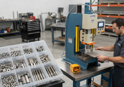
Complex Features: Dealing with Tapped Holes and Sliders

Why do manufacturers hate seeing side-facing USB ports on your 3D models?
Standard steel molds open exclusively up and down; any geometric feature facing sideways physically locks the part inside the cavity, requiring highly expensive secondary hydraulic slider mechanisms to extract it.
Designing deep, intricate die casting undercuts skyrockets your initial NRE tooling invoice instantly. Every time the factory has to build a moving side-action core to create a lateral hole, the complexity and maintenance cost of that heavy steel tool doubles.
Vertical features are significantly easier to manufacture. Integrating die casting bosses and holes facing the primary opening direction allows the liquid metal to flow around steel pins naturally. However, if the required hole is microscopic or needs precise threads, attempting to cast it directly is a massive mistake.
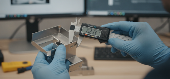
Tolerances and Shrinkage: Hitting the Blueprint

What causes a perfectly machined steel mold to produce parts that are too small?
All boiling alloys contract and compress physically as they chill into a solid state; failing to mathematically oversize the cavity beforehand guarantees every unit will miss your strict assembly dimensions.
Factory software specifically calculates this die casting shrinkage allowance before the spindles ever cut the tool steel. Different alloys contract at vastly different speeds, meaning you cannot pour zinc into a mold originally engineered to compensate for aggressive aluminum contraction.
Hitting high-end medical or aerospace limits means understanding standard die casting tolerances. When procurement directors demand absolute perfection, they usually specify nadca die casting tolerances to ensure the factory hits strict North American dimensional requirements across million-unit runs.
Preparing for Secondary CNC Machining at JC Rapid

Why must hardware teams intentionally leave extra metal on critical mating surfaces?
Raw injection rarely produces a perfectly flat, zero-gap O-ring seal; engineers intentionally add extra thickness to the CAD file so advanced mills can shave it down perfectly smooth later.
Calculating this exact die casting machining allowance separates amateur designers from commercial veterans. If you do not leave enough raw material for the cutter to grab, the cutting tool will simply skip across the surface, ruining the final fitment. Debating die casting vs machining tolerances usually ends with a hybrid approach: pour the complex shape cheaply, then utilize CNC machining to perfect the most critical sealing grooves.
Stop trying to guess these complex thermodynamic rules. Send your massive commercial assemblies to our engineering team today. We provide a ruthless, completely free manufacturing audit, ensuring your hardware drops out of our presses flawlessly and mates together perfectly.
FAQ: Honest Answers About Wall Limits and Tooling
![]()
Can I cast extremely sharp, ninety-degree interior corners on my housing?
No. Sharp interior corners create massive stress concentrations where the cooling metal will inevitably tear and crack. You must apply generous rounded radii to every internal junction to ensure structural survival.
Why does the factory request permission to hollow out the thickest part of my design?
Massive chunks of solid metal cool incredibly slowly, trapping heat that pulls the exterior walls inward, creating ugly visible sink marks. Hollowing the core ensures rapid, uniform thermal extraction.
Does adding heavy draft angles ruin the cosmetic appearance of the final product?
Standard drafting requires only one or two degrees of slope, which remains virtually invisible to the naked human eye but drastically extends the lifespan of the expensive steel extraction pins.
Will the factory tell me if my CAD file is impossible to manufacture?
Low-tier brokers will simply take your money and deliver failing parts. We actively halt production during the DFM phase, refusing to cut steel until your geometry mathematically guarantees a flawless injection cycle.


ㆍPrivacy: We respect your privacy. Here you can find an example of a non-disclosure agreement. By submitting this form, you agree to our terms & conditions and privacy policy.